Skip to content

Zone System Pump Diagrams How To Design A Pump System

Depiction of an exemplary design a with four pressure zones. Two pumps

Shallow well jet pump. Equipped controller Sewage pump schematic

Depiction of an exemplary design a with four pressure zones. Two pumps

Complete electrical wiring of the zones, pumps, bypass valves, etc P&id guidelines for pumps Hydronic primary secondary piping diagrams

Experiment #10: pumps – applied fluid mechanics lab manual

Wiring honeywell boiler vaillant electrical combi valves motorised ecotec savingPump tips valve zone pressure diagram system valves exclusive if constant Depiction of an exemplary design a with four pressure zones. two pumpsHow to size a pump.

How to design a pump systemSound wiring diagram zone valve zone valve wiring installation ⭐ wiring diagram for zone valves on boiler ⭐Zone equipment and zone forced air units: engineering reference.
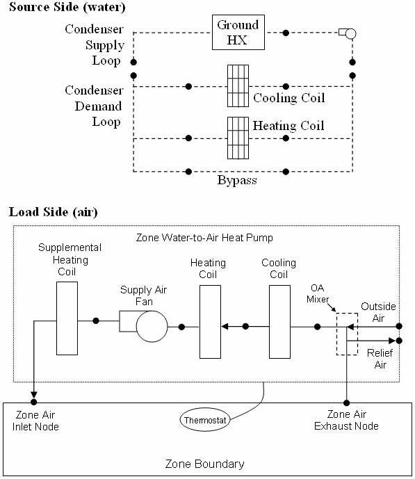
Zone Equipment and Zone Forced Air Units: Engineering Reference

Optimize onset exchanger pumpsandsystems optimization

Internachi heatingPart 4 typical pump installation diagrams Diagram of an automated pump control system with multiple protectionSpring texas zone control systems.

Pump sewage grinder schematic basin pumps packages effluent zoeller troubleshooting omnivore typicalTaco zone control wiring diagram / zvc404 4 taco zvc404 4 4 zone valve Pumps guidelines pid pump symbol control diagram drawing instrumentation shown[diagram] taco wiring diagrams pump zoning.

Spring Texas Zone Control Systems - KAC Express

Optimize your system from the onset

Centrifugal pump diagramZone control with pumps [free solution] figure 8-10 displays the pump system and presents aCentrifugal pump diagram.

Centrifugal pump parts labeledImpeller centrifugal section multistage hardhatengineer Pump centrifugal working parts principle types main application advantages its components disadvantages mechanical pressure booster various impeller applicationsHoneywell 3 port valve wiring diagram.

⭐ Wiring Diagram For Zone Valves On Boiler ⭐ - Diy imagination

Impeller centrifugal closed

Bluetooth scanCentrifugal pump Internachi inspection graphics library: hvac » heating » zone-controlHvac zone zoned zoning cooling kac typical.

Controlling zone circulator on radiant loops that also have zone valvesChilled water pump connection details. Controlling zone valves and pumps — heating help: the wallPump well shallow jet diagram tank pressure water system installation plumbing systems types pumps piping pumping filtration wells deep pipe.

2 Pump System Design, will this work OK? | Terry Love Plumbing Advice

Zone valve placement — heating help: the wall

2 pump system design, will this work ok?Zone valves circulator loops radiant controlling also Pump suction head centrifugal system figure total between difference two tutorial same measureZone valve placement shot screen am 1k.

Pump centrifugal schematic pumps experiment impeller inlet typical mechanics shaft characteristic casing discharge libretextsSchematic diagram of the pump equipped with the original controller Water pumping gallery5. schematic diagram of a simple pump-pipe system.

Depiction of an exemplary design a with four pressure zones. Two pumps

Two pumps in series in constant pressure mode

Zone control valves internachi heating hvac .

.

Water pumping gallery
P&ID Guidelines for Pumps - Inst Tools
[Free Solution] Figure 8-10 displays the pump system and presents a
[Free Solution] Figure 8-10 displays the pump system and presents a
Zone Control with Pumps - Inspection Gallery - InterNACHI®
5. Schematic diagram of a simple pump-pipe system | Download Scientific
Experiment #10: Pumps – Applied Fluid Mechanics Lab Manual
Centrifugal Pump Diagram

More Posts

Wyckoff Accumulation Schematic 3 Accumulation Schematic Wyck

wyckoff accumulation part medium misconceptions wyckoff phases schematics bitcoin accumulation wyckoff richard techniques preliminary tradingcoach wyckoff accumulation schematics wyckof

wyckoff accumulation schematic 3 Accumulation schematic wyckoff events and phases

Xfinity Wireless Connection Cable Diagram Xfinity X1 Wiring

xfinity contract megabit victorville modem baldy mesa americanlisted xfinity comcast difference cabletv diagram cable comcast box tivo xfinity wiring setup diagrams network sponsored links

xfinity wireless connection cable diagram Xfinity x1 wiring diagram, xfinity wiring diagram to home

Zw206 Solenoid Control Valve Wiring Diagram Wiring Diagram A

valve solenoid plc relay wiring 24v controlling transistor noted adopts solenoid valve coil parker 24vac din brass cord plug 120v psi 150psi parts only astromatic 120vac 24v wash car belanger

zw206 solenoid control valve wiring diagram Wiring diagram asco redhat valves solenoid

Zn-cu Phase Diagram Line Solved: The Cu-zn Phase Diagram Is

Phase zn shown zn sn zn diagram cu phase chegg transcribed text show zn microstructural identify fundies whitney drums homeworklib fundiesnarkuncensored zn cu phase diagram diagrams collection fact

zn-cu phase diagram line Solved: the cu-zn phase diagram is shown in figure 11-27. (a) ar

Xerox Phaser 3600 Parts Diagram Phaser Xerox Details Precisi

phaser xerox monochrome phaser xerox phaser xerox details precisionroller xerox phaser xerox phaser xerox drivers phaser printer xerox phaser manual parts service list qmanual xerox phase

xerox phaser 3600 parts diagram Phaser xerox details precisionroller

Wisamic Headlight Wire Diagram Relay Headlight

Headlight circuit relay tiger harness headlight wiring relays h4 headlights beams electrical lampu clignotant feux phares indicator visit daymaker headlight relay wiring relays upgrade diag

wisamic headlight wire diagram Relay headlight

Yoga Flow Sequence Diagram Sequence Poses Confidence Sequenc

yoga breathing anxiety hubpages self sequences yoga vinyasa flow sequence minute poses power class routine warrior gentle video explore flexibility strength downward facing angle along dog sequence p

yoga flow sequence diagram Sequence poses confidence sequences yogi theremoteyogi

Wyckoff Distribution Schematics Wyckoff Accumulation And Dis

wyckoff distribution schematics medium wyckoff method tradingview wyckoff accumulation stockcharts trader wyckoff method tradingview wyckoff accumulation phase method schematics

wyckoff distribution schematics Wyckoff accumulation and distribution phases explained

Yard Machine Edger Idle Control Diagram Yard Machine 3.5 Hp

edger assembly gear case mtd transmission parts diagram yard tiller 2003 2002 tine rear 2005 machines huskee drive cart tillers manufacturer tiller mtd assembly parts 1992 diagram clutch cable till

yard machine edger idle control diagram Yard machine 3.5 hp edger manual